Fronius State 307 Error: Low DC Input Voltage
Troubleshoot Fronius State 307 error code (low DC input voltage).
Insufficient DC input voltage on the inverter MPPT trackers. The unit remains in standby because solar irradiance is inadequate to reach the required DC startup threshold (Udc min).
Probable Causes
Low solar irradiance during early dawn, dusk, or heavy overcast / snow accumulation on PV panels.
String open-circuit voltage (Voc) below the minimum programmed startup voltage threshold (Udc min typically 80V to 200V).
DC disconnect switch disengaged, blown gPV cylindrical fuse in combiner box, or loose MC4 quick-connect terminal.
Diagnostic & Testing Steps
- •The inverter remains in standby or grid-monitoring mode and fails to initiate AC power injection.
- •Status LED flashes orange or yellow on the front control display.
- •Event code State 307 is logged in the Solar.web application or displayed on the local LCD panel.
Tools & Equipment Required
- ✓CAT III 1000V Digital MultimeterMeasure PV DC open-circuit voltage (Voc) and verify polarity across DC strings.
- ✓1000V Megohmmeter (Insulation Tester)Measure DC string insulation resistance to earth ground (must exceed 1.0 MΩ at 1000V).
- ✓MC4 Disconnect & Assembly ToolSafely unlatch snap-in solar DC connectors without stressing solar cable terminals.
- ✓Class 0 (1000V) Insulated Safety GlovesMandatory PPE protection against lethal DC arc flash and shock hazards.
- ✓Torx TX20 ScrewdriverRemove lower inverter connection bay cover and terminal shield.
Fast Reset Sequence: Solar Inverter Safe AC/DC Shutdown & Reboot Sequence
Before unmounting panels or beginning diagnostic procedures, attempt this manufacturer reset to clear transient microcomputer lockouts:
- 1.Step 1: Switch OFF the dedicated AC circuit breaker at the main electrical distribution panel.
- 2.Step 2: Turn the rotary DC Disconnect Switch on the underside of the inverter to the OFF (0) position.
- 3.Step 3: Wait a minimum of 5 to 10 minutes to allow high-voltage DC capacitors to bleed down to 0V.
- 4.Step 4: Re-engage the DC disconnect first, followed by switching ON the AC breaker.
- 1
Step 1: Check Weather Conditions and Array Shading
[ ] DoneVisually verify modules are free of debris, leaves, or snow blankets and confirm solar irradiance reaches at least 100 W/m².
Verification:Ambient sunlight is sufficient and the array is free of physical obstruction. - 2
Step 2: Measure String Open-Circuit DC Voltage (Voc)
[ ] DoneOpen the DC isolator and measure DC voltage using a CAT III/IV 1000V rated multimeter between the (+) and (-) string leads.
Verification:Measured DC string voltage cleanly exceeds the startup threshold (Udc min) indicated on the Fronius specification plate. - 3
Step 3: Inspect DC Protection Chain and Reset Inverter
[ ] DoneVerify continuity of DC fuses, ensure all MC4 connectors are securely latched, and turn the DC switch firmly to ON.
Verification:Inverter status LED transitions from blinking yellow to solid green as AC grid coupling completes.
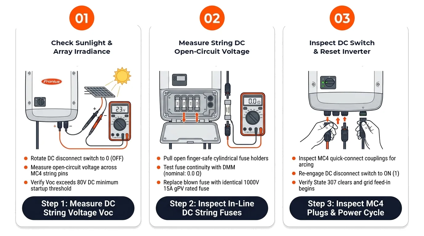
Repair Solutions
Measure open-circuit DC voltage (Voc) with a digital multimeter at each MPPT string input.
Verify continuity of inline DC fuses, inspect MC4 connector locking pins, and firmly engage the DC isolator.
Inspect roof layout for temporary shading obstructions and verify ambient irradiance exceeds 100 W/m² before re-testing.
Frequently Asked Questions
Why does my Fronius inverter display State 307 in the morning or evening?
State 307 is normal passive standby behavior at dawn and dusk when sunlight is insufficient to hit the MPPT minimum startup voltage.
Does State 307 indicate hardware failure inside the inverter?
No, this is a protective standby mode. The inverter automatically initiates power generation once the strings reach operating voltage.